The Dual Question Approach - version B
The next major version of the code (version B) kept the idea of the two checks rotating in a cycle. However, the code for the three infrared sensors was replaced with code for the two bump sensors and ultrasonic sensor. The ultrasonic sensor was pointed down at a 90 degree angle with the purpose of finding any large holes or curbs that the rover might drive into and get stuck in or cause the rover to flip over. The bump sensors were attached to front of rover to warn it when it has hit a rock, wall, or other object blocking its path. The basis of the code was kept in the same two parts where the Arduino first asked if the sensors were blocked then if it was receiving a signal from the beacon. The beacon navigation was changed slightly in that the rover didn’t try to go west but instead traveled to the direction calculated from the beacon’s information. In addition, when there was no signal for the beacon, the code was changed to go towards the last reading instead of correcting itself to go to the west or another direction. However, the hardware required to test this code was not completely finished so it was decided to continue editing the code instead of waiting to test the code.
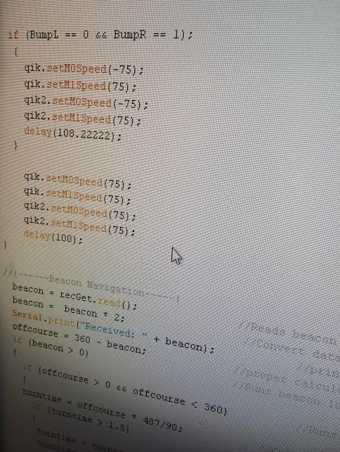
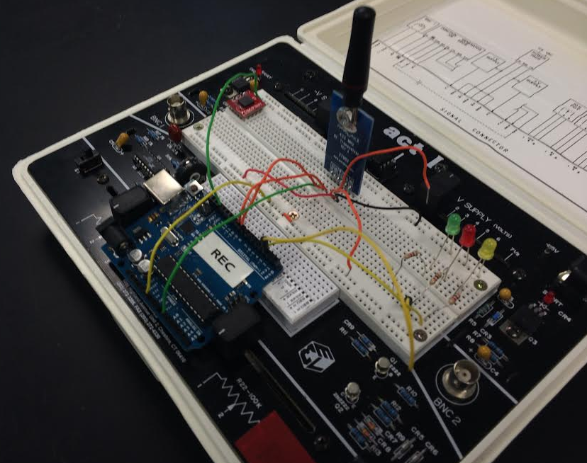
The next major version of the code with ultrasonic and bump sensors instead of IR sensors
|
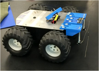
The rover with the added bump sensors mounted on
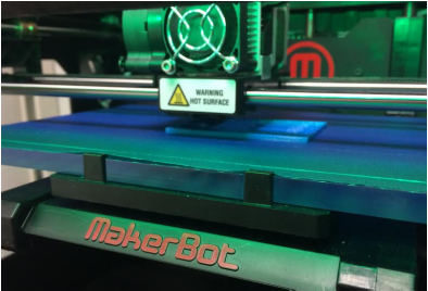
The 3D printer printing the mounts for the sensors
|
Triangulation Using Trig - version C
In the next version of code (version C), the sensor code was kept the same; however, the beacon navigation portion of the code was changed to a more mathematical approach. In the new code, the Arduino red the RSSI (received signal strength indication) of the beacon and converted it into a distance the rover is from the beacon. The rover drove forward, then red the RSSI again and calculated it into a distance. Then using the two distances from the RSSI and the distance between the points where the RSSI was red, the beacon can only be at two locations. The Arduino uses trig and the law of cosines to calculate the angle the rover needs to turn to redirect itself towards one of the possible beacon locations. It drove forward then red the RSSI again and converts it into another distance. If the distance is smaller than the last reading, the beacon is at that location. If larger, then the beacon is at the other location. The rover would then backtrack to the previous location and turn to the other direction where the beacon is. Once the beacon location is determined and the rover is facing that direction, the rover uses the magnetometer to determine the direction it is facing and uses that direction as the direction to always return to after navigating around obstacles. Throughout this beacon navigation, the rover is checking its sensors to ensure that it is not about to run into any walls or fall into any ditches. Thus the beacon navigation and sensor navigation are intertwined together to get the best path to the beacon. The rover uses less guess and check to determine the location of the beacon and thus less driving. Instead the Arduino uses math to find the exact location and navigate there while still avoiding possible obstacles making this code highly effective and efficient.
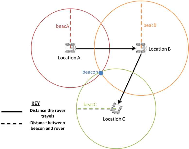
This diagram shows the idea of triangulation in that at any point RSSI could be read and converted into a distance. The beacon could then be at any point that distance away which would end up being a circle. Using three locations the beacon can be located to the intersection of the three circles.
This is a picture of the beacon. It has an Arduino Uno microcontroller (the blue box toward the left) and the transmitter (the blue box with a small antenna) as well as various other parts.
